
The combination of GPRS wireless communication network and | Internet network is used to form the street lamp remote monitoring system. GPRS network mainly completes the data acquisition task of the host at the control end of the street lamp monitoring system, and Internet network mainly realizes the data transmission task of the main controller of the street lamp monitoring system. The combination of the two networks can achieve the advantages of stable and reliable long-distance data transmission, It is a good attempt for street lamp remote monitoring system
GPRS (general parked radio system) is a standardized packet switching service. It has the function of charging according to traffic; The speed of GPRS network connection is fast; Internet network is a global system of information resources. Combining the two to form GPRS-Internet network to realize street lamp monitoring system
1、 Composition of street lamp remote system
The street lamp remote system is mainly composed of four parts: master controller, master at control end, slave at control end and data communication module. The master controller is connected to the Internet through Internet network, The host of the control end completes the tasks of real-time data acquisition and control through GPRS network. The host of the control end and the slave of the control end communicate through the existing power line transmission. The design block diagram of the street lamp monitoring system is shown in Figure 1
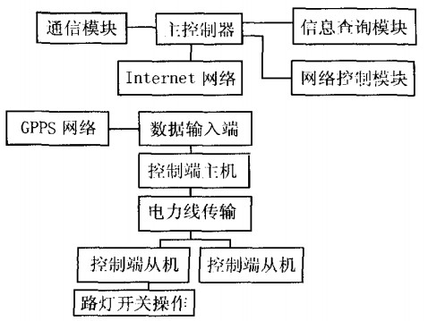
Figure 1 design block diagram of street lamp remote system
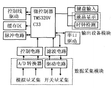
Figure 2 hardware block diagram of street lamp remote system control terminal
2、 Hardware design scheme of host at street lamp remote control end
The hardware composition block diagram of the host at the control end of the street lamp remote system is shown in Figure 2. The data input end includes analog input and digital input, which respectively send the collected data to the microcontroller through a certain conversion circuit. The control line driving chip completes the bus driving task of the microcontroller, and the serial port driving chip sends the signal to the microcontroller, There are transmission control protocol and network protocol in the microcontroller, so that the data can be transmitted in real time and through GPRS-Internet network. The main tasks of the main functional modules are summarized below
2.1 microcontroller tms320v 3
The microcontroller adopts 32-bit high-performance floating-point chip TMS320VC33 produced by TI company, which has dual power supply and two low-power consumption modes; The peripheral circuit is easy to expand, and there are two interrupt modes. The operation speed of the chip is very high. It uses the hardware part to improve the operation speed, In the past, the digital processor used software to enhance the running speed of the system. These structures of TMS320VC33 can greatly improve the ability of the digital signal processor. The microcontroller is connected with the control line driver chip to realize the driving function of the control bus. The peripheral control circuit also includes pulse circuit and buffer area. The pulse electricity is transmitted through the real-time pulse signal sent to TMS320VC33, Complete the real-time correction function of the microcontroller. The buffer area in the peripheral control circuit mainly processes various analog and digital data collected by TMS320VC33 and temporarily caches them in the buffer area. This can improve the real-time data processing ability of the microcontroller TMS320VC33
2.2 data acquisition (data input) module
The data acquisition module of the host at the street lamp remote control end mainly consists of analog quantity acquisition part and switching quantity acquisition part. The steps of analog quantity acquisition are to convert analog quantity to digital quantity through analog-to-digital conversion circuit, then send the converted digital signal to the control circuit for control task, and finally send it to the microcontroller TMS320VC33, Carry out data processing tasks; The step of switching value acquisition is to first send the collected switching value signal to the driving circuit to complete the driving task of digital signal, then filter the driven digital signal through the filter circuit, and finally send it to the microcontroller TMS320VC33 to complete the data processing task together with the collected analog quantity
2.3 output device module
After the microcontroller TMS320VC33 processes the analog and switching values collected from the data acquisition module, an external output device is required. The output device of the microcontroller mainly includes two parts: one is the liquid crystal display device and the other is the clock detection circuit. The liquid crystal display circuit displays the data processed by the microcontroller TMS320VC33 on the liquid crystal screen, The main function of the clock detection circuit is to supervise the clock signal of the microcontroller in real time, read the clock data of TMS320VC33 and calibrate the standard clock in the detection circuit.
3、 Implementation scheme of host software at street lamp monitoring and control end
The software implementation scheme of the street lamp monitoring system is shown in Figure 3. First complete the initialization task of the monitoring system, and then carry out the real-time data acquisition task to collect analog and digital quantities; Then scan the output device to check whether there are tasks in the output part. If there are tasks to be completed, deal with the corresponding output tasks; Then read whether there is the control command of the host at the control end. If so, the slave at the control end will perform the corresponding street lamp switching task; Under special circumstances, if there is a communication problem detected and the slave at the control end cannot operate normally, including exceeding the specified value in the microcontroller, the fault handling task shall be sent at this time; When GPRS information is detected in the buffer area, because GPRS information is temporarily stored in the buffer area in the form of GPRS data, if you want to communicate with the monitoring end slave, first change the data into a carrier data packet, send a new data packet to the control end slave, and then pass through the GPRS network, Transmit the transmitted data to the host at the control end. The last task is realized by the watchdog circuit software, which completes the clock calibration task of the control system by sending the corresponding pulse signal to the watchdog circuit. In this way, after completing a cycle, the software watchdog circuit will restart a cycle, restart real-time data acquisition, and so on
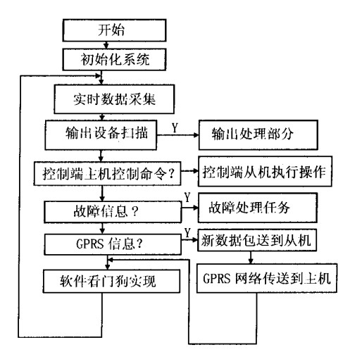
Figure 3 software block diagram of street lamp remote system control terminal T machine
4、 End
The street lamp remote control system uses the microcontroller TMS320VC33 to control GPRS and complete the data transmission function of GPRS network, and the transmission control inter network protocol in TMS320VC33, so that the data can be transmitted in real time through the network. Using GPRS Internet network can better realize real-time control than using a single network. Moreover, the transmission data is stable and reliable, It has the characteristics of strong real-time data acquisition


Email:service@juyingele.com
Tel:010-82899827/1 4006688400
Add:Block B,Jinyu Jiahua Building, Shangdi, Beijing 412
 Official Wechat
 Tmall shop
 JD shop

