
Abstract: the landscape lamp controller is composed of single chip microcomputer, battery management and landscape lamp driving module. The single chip microcomputer realizes the management of battery and landscape lamp by controlling each functional module. The detection unit understands the operation status of the wind turbine and solar panel, manages the charging and discharging of the battery, the discharge of the wind turbine and its display instructions. The address dial sets the node address. The data transmission module transmits the stored equipment data to the block master node controller, and then the master node controller transmits the data to the monitoring. With the increasing urban area, the centralized control and management of lighting in various landscapes are becoming more and more difficult. Often, the lighting in many cities or scenic spots is not opened in normal seasons, but only on weekends or national holidays, which increases the difficulty of maintenance personnel. The landscape light control system (landscape lighting centralized control system) developed by Juying electronics company adopts rtu6640, which integrates communication technology, intelligent control technology, field sensor detection technology and microcomputer chip technology, adopts mobile wireless network, and is composed of host computer management software, signal repeater, ADSL network, mobile communication network and execution terminal.
introduction
At present, the prominent problems of urban landscape lamps are the consumption of conventional energy, the cost of cable wiring and the huge project. With the development of new energy development and utilization technology and high-power LED technology, solar energy and wind energy are used as the power supply of landscape lamps, and high-power DC LED bulbs are used as the light source of landscape lamps, so as to comprehensively reduce the energy consumption of landscape lamps.
1、 Hardware structure of controller
1.1 frame structure of controller

Figure 1 Structure of landscape lamp node controller
The structure of landscape lamp node controller is shown in Figure 1. The single chip microcomputer realizes the management of storage battery and landscape lamp by controlling each functional module. The detection unit understands the operation status of the wind turbine and solar panel, manages the charge and discharge of the battery and the discharge of the fan, and is instructed by the display unit. The address dial sets the node address. The data transmission module transmits the stored equipment data to the main node controller of the block, and then the main node controller transmits the data to the monitoring center.
1.2 introduction to main functional modules
1) MCU part
Single chip microcomputer is the core of landscape controller. C8051F020 of Cygnal company is adopted. It has fast operation speed, large memory storage space, convenient debugging and industrial working temperature range (i.e. 45 ~ + 85 ℃); The chip integrates multi-channel 12 bit and 8-bit A / D converters without adding ADC chip; Two enhanced UART serial ports and one SPI serial bus integrated in the chip can be used for data transmission between the controller MCU and its slave devices.
2) Battery management module
There are many charging methods for the battery. Based on the factory charging characteristic curve of the specific battery, according to the acceptable charging current of the battery in a certain time or stage, the controller adjusts the actual charging current in stages to approximate the charging characteristic curve. When the battery voltage reaches the control point voltage, the battery turns to trickle charging. The battery management module selects the intelligent fast charger ltc1325 of linear company,
The single chip microcomputer is used to control the rapid charging process of the battery, as shown in Figure 2.

Figure 2 battery management module
Working principle: C8051F020 and ltc1325 transmit instructions and data through instruction word and status word. The total length of the control word is 22 bits, including all the information of the control ltc1325. The status word represents the measured parameters of the battery and the state of the charger, with a total length of 8 bits. The command is sent to ltc1325adc through serial interface to process the collected signal of battery, generate 10 bit reading and chip status word, and send it to single chip microcomputer. In the charging mode, c805if020 understands the voltage and current of the battery in real time according to the returned status word. Then select the charging rate and charging current suitable for the battery state, and send a command to ltc1325 through the serial port to make the charging current always approximate the charging characteristic curve of the battery. When the battery voltage reaches the control point voltage, the battery turns to trickle charging.
3) Landscape lamp driver module
The design adopts the method of pulse width modulation constant current drive to regulate the current of high-power series LED (Fig. 3). When the external environment changes, the peak value of the pulse driving current will change. In order to keep the average driving current constant, change the duty cycle of the driving current in each pulse cycle to make its average current equal in each pulse cycle.
Cs700c / cs700i is a three-way high-power LED constant current driver, which can drive 350mA and 700mA LEDs. Its working current can be set by external resistance, and the working current can be adjusted steplessly. The LED is directly driven by the external FET, which has high reliability and convenient heat dissipation design. The external input corresponding PWM signal driver can control the operation of the LED, and the minimum ripple can be less than 5omv through the external filter capacitor, which can effectively ensure the working life of the LED.
Pwmr - red PWM control signal input, low level active, 3.3V TTL;
Pwmb: Blue PWM control signal input, low level effective, 3.3V TTL;
Pwmg: Green PWM control signal input, low level active, 3.3V TTL:
Cs700c / cs700i is selected as three-way high-power LED constant current driver. The purpose is to provide constant average driving current for semiconductor lighting LED under the condition of external environment change, such as power supply voltage jump or lighting LED light source parameters with ~ fixed deviation, so as to ensure that its brightness and color do not deviate; By adjusting the duty cycle of driving current, the color of LED can be changed flexibly.
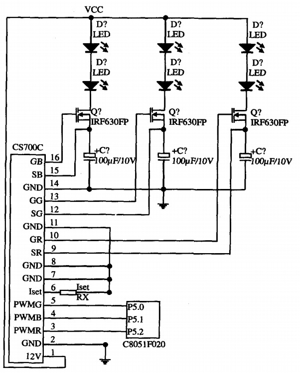
Figure 3 landscape lamp driver module
2、 Software part
The software system adopts functional modular design, which will slightly increase the length of software code, but it is conducive to software maintenance, management and transplantation.
3、 Conclusion
The scenery complementary controller of urban landscape lamp designed with new energy and high-power DC LED bulb can reduce the energy consumption of landscape lamp and has high economic and practical value.


Email:service@juyingele.com
Tel:010-82899827/1 4006688400
Add:Block B,Jinyu Jiahua Building, Shangdi, Beijing 412
 Official Wechat
 Tmall shop
 JD shop

